
IK Arm Rig set-up with Forearm Twist!
Rigging Assessment 1
Creating an arm rig with an IK system and additional forearm twist as the hand rotates.
Attempting the use of an ik handle implies a solution that requires a selection of 3 joints with the middle joint as the bending point of the rig.
IK Arm Rig without a Forearm Joint:

However, for this tutorial we will rather be focusing on using an IK RP solver solution, with a forearm joint intact, to enable a natural twist deformation chain-effect from the hand’s rotation following through the wrist and the forearm.
By including a 4th joint in the ik handle solution, the arm would end up bending in an undesired manner since an ik handle does not function correctly with suddenly 2 joints between the start and end points of the solver.
Fortunately the handle is merely a visual display to indicate which joint will act as the bend within the calculated solution. What we really need to worry about is in fact the effector which is the goal for the solver.
The effector can be found in the outliner parented under the middle point joint, the joint where the rig bends with the ik handle. With this we can simply choose on which joint we would like the ik handle to display so as to keep consistency with a visual logic.
So lets start rigging!
STEP 1:
Setting up the joints:

For this arm rig tutorial we have no need to worry about any of the joints needing to be in World Orientation.
- Create 4 joints for the left arm of a character by using the joints tool with default settings. This will create the joints to be already Oriented to Local Orientation with the X-axis running up the joints along the hierarchy. Always turn the the local rotation axis display to double check that the joints are indeed oriented correctly to avoid later problems.
- Name the joints based on the image above, from left to right:
- l_shoulder_Joint
- l_elbow_Joint
- l_foreArm_Joint
- l_wrist_Joint
Considering that we will only be focusing the arm for this rig, there is no need for hand joints to be created as well at this point since it is a whole separate extended part of the rig that functions independently beyond the wrist joint. For visual purposes however, a hand will be included to show off the functionality of the Hand Control that will be influencing the rotation of the hand based on the manipulation of the Control from wrist.
STEP 2.
Setting up the Controls: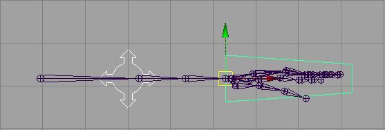
- Create two separate shapes out of curves that will be suitable as controls for the hand and the elbow and name them accordingly:
- “left_Arm_IK_Control”
- “left_Elbow_IK_PV”
2. Delete construction History on both Controls and Freeze their Transformations to reset their input values for clean calculated connections between controls and the joints later on.
STEP 3.
Rigging the Arm with an IK Handle.
Now that everything has been set up properly, we can start rigging the arm with the IK Handle Tool.
- First, set the preferred angle on the elbow by rotating the arm inwards in the Y-axis from the elbow joint to indicate which way the arm should bend. With the elbow Joint rotated and still selected, hold down the Ctrl key on the keyboard and right click to bring up and options menu. Click on “Set Preferred Angle” and reset the joint’s rotation back to 0 through the Channel Box. Do NOT “Ctrl Z” to undo the joint’s rotation values as this will also undo the “Set Preferred Angle”. If we really want to be on the safe side, simply select the root joint of the arm, which would be the shoulder joint, and apply a Freeze Transformation.
- Create an IK Handle, set to RP Solver, clicking once on the shoulder joint to start Handle, and once on the forearm joint to complete the Handle.
- Find the effector in the outliner.
- With the effector selected, modify it’s pivot point location by pressing “insert” on the keyboard. Snap the pivot point of the effector to the wrist joint and press “insert” again to complete the modification of the pivot point.
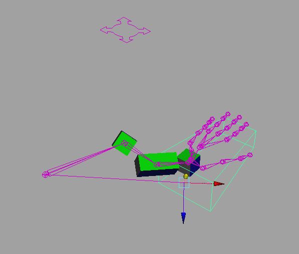
- The display of the IK Handle has now moved the location of the wrist joint while allowing us a forearm joint to enable the natural forearm twist effect that would come from the wrist.
Functional IK Handle with forarm joint:

STEP 4:
Preparing the Hand Control:
- Group the Hand control to itself to create a Buffer Group for protecting the clean inputs on the Control.
- Parent Constraint (maintain offset off) the Hand Control Buffer Group to the wrist joint.
- If the Hand Control flipped in rotations, simply manually rotate it back to how it should fit around the hand and apply FT. The Buffer Group should still contain the correct inherited Local Orientation values from the wrist joint, leaving the actual Control with clean input values.
- Delete the Parent Constraint as it is no longer needed. If left alone, it would cause problems later so its better to get rid of it now.
Making the Controls in charge of the IK Handle for an Animator to manipulate the Arm.
- Make the Elbow Control in charge of the IK Handle with a Pole Vector Constraint, making sure to select the Control first as the master in the constraint.
- Point Constraint the Hand Control (selected first) to the IK Handle to take over the translates control.
- Orient Constraint the Hand Control (selected first) to the wrist joint to enable rotation control on the hand from the wrist.
STEP 5:
Forearm twist Blended Constraints:
Purely for visual display, this tutorial is designed to show off the effects of the forearm twist solution with simple colored cubes parented to the joints.
- Parent wrist cube to wrist joint.
- Parent forearm cube to forearm joint.
- Parent forearm cube to elbow joint.
Setting up for blended constraints:
- Select Hand Control and Orient Constraint to forearm joint.
- Select elbow joint and Orient Constraint to forearm joint.
Offset constraint weights values for a smooth forearm blend twist solution:
- Select the forearm joint or the Orient Constraint and view the foreArm_Joint_orientConstraint1 settings in the under SHAPES in the Channel Box.
- Change the Left Arm IK Control (the hand control) weight from a complete 1 influence, to 0.7
- Change the elbow joint weight weight from a complete 1 influence, to 0.3
- The hand control on the wrist has more influence over the twisting follow-through effect of the forearm, therefore the constraint weight value input coming from the hand control should be higher than the input value coming from the elbow joint as it is further down the hierarchy in the twist from the wrist when the hand rotates.
Added sophistication from the Elbow Control:
- Group the Elbow Control to itself to create a Buffer group, protecting the input values of the Control.
- Reset the Center Pivot of the Buffer group by going into the Modify menu tab and selecting “Center Piviot”.
- Select the Hand Control and apply Point Constraint to the Elbow Control.
- This should allow the Elbow Control to follow the Translates of the Hand Control while additional control and refined poses can be achieved through separate manipulation from the still independent Elbow Control.
We now have a complete functional IK Arm Rig!!!
RIG COMPLETE…
Even Eleven FK Spine Rig
Rigging Assessment 1
Eleven joints spine setup, what to expect?
The proper functionality of the rest of the character rig parts are solely dependent on the correctness of the spine rig.
The spine rig is litterally the “Spine” of the character. Meaning that the spine is what holds everything together and therefore it is extra crucial to understand the joints, local and world orientation, types of constraints and above all, understanding the difference between Inverse Kinematic and Forward Kinematic.
For this tutorial we will be focusing on an FK rig system.
FK – hierarchy (blended constraints).
Can shift keys to break joints, making one part of limb to move first then the next part to move later. One thing moving after another up the chain, also used for breaking joints in animation.
EXPLAINING CONSTRAINTS:
Straight parent (Translate and Rotate): select the child then the parent; apply – parent will drive the child will follow. In multiples selections, select all the children first then the parent as the last selection then apply the straight parent command.
Parent constraint (Translate and Rotate): Select the master first then the slave and the master will make the slave follow. In rotation, the slave will follow the world orientation in, relation it will stain in line with the rotation and pivot around the world of the master.
Point constraint (Translate): master first then the slave – in translates the slave will follow where the master goes.
Orient constraint (Rotate): master first then the slave – the slave will rotate as the master rotates but it will stay at the same pivot and rotate on its original spot.
EXPLAINING JOINTS AND THE IMPORTANCE OF WORLD AND LOCAL ORIENTATION:
The Root joint is for deformation purposes and the hip joint is so we can wiggle the hips independently from the rest of the rig system.
- If a joint has multiple children, we call it the core joint.
When setting up a spine joints system, it is important to know, always:
- The root joint and chest joint is oriented to world because they need to communicate with the “outside world” orientations. These two joints are also the parents for the leg and the arm to attach to.
- The rest of the joints are by default built to behave in their own local orientation when the joints tool is set to default settings.
LETS START THE RIG!!
This rig will be solved by Control curves, constraints and hierarchy parenting.
STEP 1:
Setting up the joints.

- The locators indicate where the joints need to be placed to start forming the spine by using the create joints tool and point snapping to the locators.
- The crotch (tail bone) is created separately and parented as a child to the root joint: Select the root joint, shift select the crotch joint and press “p” on the keyboard. Another way to parent would be to go into the outliner and middle mouse drag-drop the crotch joint onto the root joint. The root joint is important because it is the ultimate parent joint of the whole character’s separate rigs. Simply for visual reference, we will include the neck and head joints to see what we are working with, however it will not be rigged with controls for this tutorial as we are only focusing on the spine.
- Double check the local orientation for the spine, the x-axis should be running up bone the of the joint system as illustrated in the above image. As discussed earlier, the exceptional joints to be oriented to world space should be the the crotch joint, root joint and the chest joint.
Hierarchy in the outliner:
Name the joints according to functionality placement and hierarchical number.
Reading the hierarchy in the outliner based on the joints we created in the scene, we have:
- A root joint
- A crotch joint parented to the root joint as a child
- 11 spine joints
- A chest joint
- Additional 4 joints for the neck with a head base joint to complete the structure of the spine
STEP 2:
Setting up Controls to manipulate the joints.
Control shapes are constructed with a bit of modeling by using the ep or cv curve tool. Depending on the simplicity of the rig it is common to use the existing NURBS primitive circle as a base starting point creating custom shapes by making small changes to the shape to fit the purpose of the control which would include a point of direction where applicable.
1. Create and name control curves:
- Global Control – “global_Control” – Snap to Grid
- Hip Control – “hip_Control” – Snap to Root Joint (To manipulate the whole spine (upper body) from its root in the hierarchy).
- Independent Hip Control – “independent_Hip_Control” – Snap to Independent Hip Joint
- Back Spine Control – “spine_Control_1” – Snap to Spine Joint 1
Fit the curves in place around the spine:

2. Clear construction history
In rigging it is important to delete the history and freeze transformation on anything that has been made for the purpose to be included in the rig. A rig requires a clean connection for any sort of maths in the calculation to match up, otherwise there would be enough room for risk to potentially unexpected result, the rig could break, or problematic none fixable issues could surface later in the rigging process which would require intensive reverse engineering to find the problem or start all over again. A pain we should like to avoid as much as we can help it.
- Select the newly created control curve, go to edit in the menu bar, delete by type, and select History. This should clean up all the construction history created on the curve previously.
- With the curve still selected, go the the modify menu bar and select Freeze Transformations. This will reset the objects location, rotation and scale values back to 0 without actually affecting the general shape.
3. Repeat in the instructions in number 2 on all the control curves before commencing any further. Make sure all the shapes are clean without any left over input values.
STEP 3:
Preparing the Controls for rigging:
By default, any new created object with in Maya is set in World Orientation.
So before we move on, we need to understand and consider the World Orientation of the Controls that we would like to form a connection to the Joints of which most are set to Local Orientation.
We need to find a way to allow the Controls to form a connection with the Joints without needing to use the maintain offset setting in the constraints menu option settings. The less we need to depend on such automatic “fix for me” settings, the more we can understand by self-knowledge how to trouble shoot and solve related rigging issues.
Spine Controls:
Trick the Control Curve by making it think it is Oriented to Local space for considering correct calculations while maintaining World Orientation in actuality.
- Group Spine_control_1 to itself to create a buffer group.
- Pres insert on the keyboard to modify the pivot point without moving the object: Re-snap pivot point back on top of spine_joint_1. Press insert again to deactivate the modify pivot function.
- Apply a parent constraint between the Control Buffer Group and the Joint, with maintain offset off. The Control Curve will flip to match the joint’s Local Orientation. (Select the joint first, then shift-select the control curve; because we want the control to inherit the information of the joint. The control is the slave of the joint as the master)
- Because the Control Curve’s World Orientation and input values are protected by the Control Buffer Group, we can use component mode (F8) to manually change how the Control should fit around the Joint. Activate component mode, select all the edit points and rotate the Control Curve 90 degrees in the Z-axis. Rotate the direction of the Control in the X-Axis if applicable.
- Delete parent constraint because we no longer need it.
- Duplicate spine_Control_1 and snap to spine joint 6. Rename Control to “spine_Control_2”. Pull the new Control out of the Buffer hierarchy. Delete History and Freeze Transformations. Repeat instructions from 1-5.
- Duplicate spine_Control_2 and snap to joint 11. Rename Control to “spine_Control_3”. Pull the new Control out of the Buffer hierarchy. Delete History and Freeze Transformations. Repeat instructions from 1-5.
After completing the instructions outlined in 1-7, turn on the local rotation axis display on the Control Curves to double check that they are indeed tricked and now set to Local Orientation in order to communicate a clean and direct connection to the Joints.

*Tip: Sometimes it’s easier to see what you are doing by marking your destination before attempting to snap one object to another.
Create two temporary locators, one snapped to joint 6 and the other snapped to joint 11. Now we can clearly see where the joints are without guessing. Delete the locators after the Controls are set in place.
STEP 4.
Rigging the Controls to manipulate the Joints.
Control curves drive the joints (orientation constraint) – joints translation drive control curves for a visual appeal (point constraint):
- Orient Constraint the Control Curves to their respective Joints (selecting Control first).
- Point Constraint the joint in turn, to the Control Curve (selecting joint first).
STEP 5.
Setting up and preparing for blended constrained joints with orient constraints:

STEP 6.
Calculating and applying the weighted blends to the joints for smooth calculated deformation curved bend through the spine:

STEP 7.
Hip Controls.
The hip Control is the main parent for the spine joint system.
- Repeat STEP 3 number 1-5 (naming convention to be considered for the Hip Control and Hip Joint instead). Technically the Hip Control does not need to be tricked to Local Orientation since it will be connecting to the Root Joint which already exists in World Orientation because we made sure of that from the start. But we will do this just for good practice and because we can.
- Repeat STEP 3 number 1-5 (naming convention to be considered for the Independent Hip Control and Independent Hip Joint instead).
STEP 8.
Hierarchy and final integration of the Controls:
1. Make the spine_Control_1 child of the independent hip control. Offset occurs in the translates…?
Alternatively:
- Parent Spine Control 1 to the Independent Hip Control
- Remove Point Constraint on Spine Control 1 in relation with Spine Joint 1
- Freeze Transformation on Spine Control 1 to remove offset caused by parenting
- Reapply the Point Constraint
- Translates are now clean (not that it mattered) But we keep it clean because we can
2. Parent Independent Hip Control Buffer Group, to the Hip Control.
3. Parent Hip Control to Global Control.
We now have a complete functional and sexy flexy Eleven Joints FK blendy Spine Rig!!!
RIG COMPLETE…
FK SPINE RIG SETUP
PDF: FK_spineRig_Tutorial
This is a FK Spine Rig DRAFT.
The proper functionality of the rest of the character rig parts are solely dependent on the correctness of the spine rig.
The spine rig is literally the “Spine” of the character. Meaning that the spine is what holds everything together and therefore it is extra crucial to understand the joints, local and world orientation, types of constraints and above all, understanding the difference between Inverse Kinematic and Forward Kinematic.
IK vs FK:
FK – hierarchy (blended constraints).
Can shift keys to break joints, making one part of limb to move first then the next part to move later. One thing moving after another up the chain
IK – its name Implies inverse kinematics
- Subvert hierarchy.
- IK gives sticking point (for walking typically the only kind of set up you need for legs.)
- Can’t do breaking of joints with IK.
If you are creating a character walk cycle you are going to need an FK setup for the arms so you can break the joints (after key poses), spread out the animation and offset keys.
Constraint Theory:
Straight parent (Translate and Rotate): select the child then the parent; apply – parent will drive the child will follow. In multiples selections, select all the children first then the parent as the last selection then apply the straight parent command.
Parent constraint (Translate and Rotate): Select the master first then the slave and the master will make the slave follow. In rotation, the slave will follow the world orientation in, relation it will stain in line with the rotation and pivot around the world of the master.
Point constraint (Translate): master first then the slave – in translates the slave will follow where the master goes.
Orient constraint (Rotate): master first then the slave – the slave will rotate as the master rotates but it will stay at the same pivot and rotate on its original spot.
Joints and orientations.
The Root joint is for deformation purposes and the hip joint is so we can wiggle the hips independently from the rest of the rig system.
- If a joint has multiple children, we call it the core joint.
When setting up a spine joints system, it is important to know, always:
- The root joint and chest joint is oriented to world because they need to communicate with the “outside world” orientations. These two joints are also the parents for the leg and the arm to attach to.
- The rest of the joints are by default built to behave in their own local orientation.
Setting up the spine joints:

Create the spine joints and name them accordance, by following the above image.
- The crotch (tail bone) is created separately and parented as a child to the root joint. The root joint is the ultimate parent joint of the whole character rig body.
- Because this spine rig is FK, hierarchy based, I am not dependent on any kind of IK handles or solvers.
- This rig will be solved by Control curves, constraints and hierarchy parenting.
Setting up Controls for the spine.

- Create control curve shapes:
- Snap Back Spine Control to Spine1_joint.
- Snap Independent Hip Control to indHip joint.
- Snap Hip Control to Hip joint.
- Global control remains at default construction location; 00.00.00 on grid.
- Freeze Transformations and Delete History on constrols for clean inputs.
Next I need to think about the Joints orientations compared to the controls I just created which by default anything created new would be set in world orientation.
I need to find a way to make the controls constraint with the joints on local orientations without needing to use the maintain offset setting in the constraints menu option settings. The less I need to depend on such automatic “fix for me” settings, the more I can understand by my own knowledge how to trouble shoot and solve a rigging issues.
This will also provide me with a larger self comprehention of the rig im creating, allowing me to know why something worked, why something didn’t work and understaning how it worked when I applied a different solution than an automatic button that did everything for me.
Back Spine Control Curves:
Group the Back Control curve to itself, select spineJoint1 and shift select the new buffer group in the outliner. Apply a parent constraint with maintain offset off, because we want the buffer group to snap into place, forcing the control to allign with the joints local orientation.
(Despite appearance, the curve itself has no idea that its translates actually changed, so all its inputs are still at zero value).

In component mode I can now select all the vertices and rotate them to fit the curve around the spine chain (all its inputs still unaffected) now the curve is the same on local orientation with the spine so no later nasty flips will occur)

- Delete constraint because now it has finished with doing its job so I don’t need it anymore.
- Make sure the duplicate curve in the buffer is the correct name which should be backControl_1
Duplicate the curves again and snap backControl_2 to joint 4 and backControl_3 to joint 7
(so we have 2 joints open in between).

We are now going to apply an orient constraint for the backControl_1 to the spineJoint_1
Because it’s a constraint: (Master first (curve) then slave (joint)).
- It needs to be an orient constraint because I only want to affect the rotation values for this connection and not the translates as the joints need to know their translates location in accordance to world space.
- Select Back Control 1, shift select the joint I want it to control, spine2_joint.
- Apply Orient Constraint, maintain offset off, because I already ensured for the orientations to match up in order not to get a mathematical offset to occur.
- Repeat Step 1 and 2 for back Control 2 and 3.
Controls get left behind when I rotate another curve in the hierarchy so I need to parent the curves to each other in the hierarchy to make them follow in relation with each other when one or the other is used to control the joints.

All I need to do in Outliner is drop Control 3 on to Control 2 and drop 2 into Control 1. (1 will now be in charge of 2 and 3, 2 will above be in charge of 3 and 3 will rotate by itself.

I can now add the weighted blend properties of the joints in relation with the curves.
Orient constraint: (don’t need maintain offset)
BC1 to joint 2 and 3
BC2 to joint 2 and 3
BC2 to joint 5 and 6
BC3 to joint 5 and 6
- The joint closer to a curve will have the most blend weight
- ie: Jnt2 is closer to BC1 and should have a stronger blend value influence.
Jnt3 is closer to BC2 and should have a less influence value from BC1 and a stronger influence value from BC2
- Repeat the same theory for the rest of the joints blend with the backCurve2 and 3.
FK SPINE
Controls orient constrained to in between Joints, Weighted Blends: [ 0; Zero ]

FK SPINE
Controls orient constrained to in between Joints, Weighted Blends: [ 1; Default ]

FK SPINE
Controls orient constrained to in between Joints, Weighted Blends: [ Modified ]

I used these numbers to blend the rotation calculation to control how smooth I wanted the bend in the spine to be when I use the controls to rotate and manipulate the spine:
Joint 2 Back Control 1WO – 0.7
Back Control 2WO – 0.3
Joint 3 Back Control 1WO – 0.3
Back Control 2WO – 0.7
Joint 5 Back Control 2WO – 0.7
Back Control 3WO – 0.3
Joint 6 Back Control 2WO – 0.3
Back Control 3WO – 0.7
Independent Hip Control:
The independent_Hip_Control needs to control the indHip_joint.
– The control curve is still in world orientation and therefore it does not yet match up with joint which is set to local orientation.
– I can’t rig the control until I change that. I can do this by simply repeating the same steps I used for the Back Control curves.

Refer to image above to see where the next steps will end up.
- Group the independent Hip Control to itself to create a buffer group.
- Select indHip_joint and then the buffer group; apply parent Constraint.
- Leave maintain offset off to make the control flip in to place on to the joint, the rotation of the control is not correct because of the curve’s world orientation.
- But the data is still protected by the buffer group with zero input values, so I can now manually change the control’s orientation to match the joint’s local orientation and as a result the control should be in the correct rotated position.
- In component mode I can rotate the control curve 90 degrees in Z in appearance while the actual inputs still remain unaffected when I exit component mode.
After completing the steps, delete the constraint which is no longer needed. If I don’t to this and forget it by leaving it in there, the constraint will actually cause calculation problems and make the joints flip when I try to constraint the control to the joint regardless newly matched up local orientations.
– Complete the independent Hip Control by Orient constraining it to the indHip_joint.
At this point however, the back Curves in turn are now left behind when I rotate from the new point of the hierarchy, the hip Control.
- The joints rotate, the back controls stay behind. Make the curves controlling its assigned joint remain in location with the joint when they are rotated in hierarchy by the hip Control.
- Select spine2_joint; shift select backControl_1 – > point constraint.
- Select spine4_joint; shift select backControl_2 – > point constraint.
- Select spine7_joint; shift select backControl_3 – > point constraint.
FINALIZING HIERARCHY:
- The hip Control is the main parent for the spine joint system.
- The root joint always needs to have a world orientation by default because it will have the rest of the character rig set up parts integrated on this joint as a separate step.
- For this reason the root joint is already reoriented to world orientation at the start so it can match the orientation of the hip Control to manipulate the whole spine (upper body) from its root.
Hip Control:
- I want to have the control influence the translate values and the rotations of the spine rig.
- Parent constraint the hip Control to the hip.

Hierarchy:
- As the parent of the Back controls, select Back Control 1 and make that curve a child, with its hierarchy, children of the Hip control.
- Not including the independent Hip Control in this selection because I would like it to rotate the joints independently from the rest of the hierarchy.
- Separately by itself, parent the independent Hip control to the Hip control so it is not left behind, allowing for the hip control to be the ultimate parent for the spine from the root due to Hip control’s parent constraint to the root joint.
(While still leaving the independent hip Control indented as an individual selection in the hierarchy).

Global Control:
- Make the Hip Control child of the global Control. (With the hip Control’s children in the hierarchy already following).
- Select hip Control, straight parent to global Control.

Clean up the Outliner:
As of yet, the global control scale does not work to uniformly scale the whole spine joint system with its controls in proportion.
- Simply now, include the joints in the global Control hierarchy by parenting the joints to the global Control.
- Leave out the control buffer groups because it will break the rig otherwise when scaling and is not necessary in the hierarchy for scale to function properly.
Global control is now the ultimate parent of the whole hierarchy, a complete and clean
FK Spine Joint Rig Set Up.
Clean Final Outliner: [Closed]

Clean Final Outliner: [Open]

IK ARM RIG SET UP
This a simple Inverse Kinematics rig set up for an arm of a character.
Setting up the joints for the arm joints system.
Joint tool.

Before starting, bring up the options for the skeleton joint tool.
– Reset the tool to be at default settings, this will ensure that the chain of joints created will automatically be oriented to local orientation which means the X-axis of will point down the bone and the Y-axis pointing up.

Create the joints for the arm by following the image above.
- l_shoulder_bnd_jnt
- l_elbow_bnd_jnt
- l_armIK_bnd jnt -> This is the joint to which the ik Handle would attach.
- l_wrist_bnd_jnt
- l_hand_bnd_jnt
(Finger joints can be added for a more advanced arm and hand rig).
Because this is a rig that needs to rotate just like the leg, im going to use a Rotation plane ikHandle.
Rotation Plane solver:

With the tool settings first reset to default for a fresh tool, change the ik solver to be set to ikRPsolver for rigging the arm.
- By skipping the elbow joint, the solver is allowed to make joints behave like a natural bending arm would.

- So use ikRPsolver from shoulder to the armIk joint I created before the wrist for this purpose. At make sure the arm bends right by setting the preferred angle.

Rename the ik handle to l_armIK_handle so I can keep my work and outliner clear.
CONTROLS.
Ik handles essentially need to be able to be manipulated from another level of control for the animator to easily get around the rig and use it with easy selectable control without potentially breaking the rig.
- Controls can be revolved manually from self-constructed cv curve shapes, or in some cases like the ikArm control, it is simply a pre-made nurbs circle, basic but clear.
- It is usually up to the rigger to determine the look of the rig and what shapes are to indicate specific control
For this arm rig any shapes would suffice as this set up is quite a simple rig.
- Create the shapes.
- Snap arm control on top of the armIk joint because this is the point where the ik is created and from where I want to easily manipulate the arm and wrist control for basic character posing.
- After everything is in place, delete the construction history and freeze the transformations so there is no more data left on the controls to cause future rigging problems.
- Rename the controls according to their purpose in what they would be doing.
- l_armPV_cntrl
- l_arm_cntrl
Arm elbow Pole Vector Constraint:
Pole vector constraints are used as added control to translates of the elbow joint whenever the armIk control is used to bend the arm.

Select the control (master), then the object to which you want to constraint the control shape to (the slave), and apply command.

I want allow the armPV Control, to control the rotation plane of the ikHandle. Visually and technically it means the elbow would point at the control in the local x rotation.
- Select Elbow Control (master of the ik rotation plane)
- Shift select l_armIK (slave of the control)
- Apply Pole Vector Constraint.
Arm Control with a Point Constraint:
A parent constraint is to be used in this case for the arm control because I am interested to in making the control to be in charge of both rotates and translates of the ikHandle.
- Select l_arm_cntrl
- Shift select l_armIK_Handle
- Apply parent constraint.
There is still no control over the hand, it is stiff and not animator friendly.

Solution:
Single Chain Solver
A solver which is used to create control ik handles from only one joint to the next.
- Use the ik Handle tool with its solver settings changed to SCsolver.
- Create the single chain ik Handle from the l_armIK_bnd_joint to the l_wrist_joint.
- Name ik handle l_wristIK_Handle.
Buffer group (grouping something to itself)
Anything new created in Maya is in world space (an empty group node, a null node)
* It is used to protect the information of the object inside that group. So whatever I do to that group, connecting it to other objects, the object will remain unaffected.
- Group the two IK Handles together which would then act as the buffer group. Name it l_armIK_grp.
- Now we want this “pocket universe” to rotate from the correct point of rotation (l_armIK_jnt).
- By default the centre pivot of the group is at 0 on the grid as the default location for anything new that is created.
- Point-snap the pivot of the l_armIK_grp to l_armIK_bnd_jnt.
The control is the master of the l_armIK_grp

Parent Constraint
- A command which Constraints rotation and translation as the parent controls the child to the buffer group.
- Select arm Control as the master
- Shift select buffer group containing the ik Handles
- Apply parent constraint.
Refer to above image to see the results of these steps.
Complete IK arm Rig Set up:

Cleaning up after is very critical. Always make sure objects are named properly, history is cleaned and freeze transforms when applicable.
To finish off, lock and hide unnecessary attributes for a clean finalized character arm rig.
IK inverse Kinematic Leg and Reverse Foot set up
IkLegAndInverseFootRig_tutorial PDF
How to set up an IK leg and reverse foot control Rig:
The theory covered in this tutorial is about using the IK Handle tool with its different solvers to solve and achieve the desired results for the leg and foot rig along with additional connections, constraints and parenting to finish off the rig.
Before I start anything I would have to ensure that I have the proper joints set for a leg and a foot ready to be rigged.
Leg Joints set up
Create joints for the leg set up, with the joint tool settings set to default. Starting at the hip, ending at the toe joint.
Rename joints accordingly as the left leg bind joints.
Parent the l_hip_bind_joint to the the root_bind_joint to link the leg to the root. (Other parts of the character will also be incorporated separately to this root joint).

Inverse Foot Joints set up
From this point I can start to set up the joints for the foot, however this would need to be done separately.
Make sure to hide the leg joints on another layer. In this example I have locators which mark exactly where the joints for the foot need to be laid in the scene in relation to the joints of leg.
It is important to always name joints accordingly before moving on. Keep workflow and naming conventions consistent, because it is crucial for the purpose of trouble shooting and problem solving later down the track.
How to proceed:
First I have to understand the settings for the joint tool I have to use next and why I would choose to use it in that particular way. Below, I have an example of the results from the two options I can use to build the joints for the Inverse Foot.
The first example on the left, the joint tool is used at default, as the same with the leg joints, for local orientation so as to have the x always pointing down the bone.
In the second example to the right, the tool is set to make the joints orientations behave according to world space orientation.

Based on the image above, thinking ahead I would have to decide which result would suit my solution better. Ideally I would later like to incorporate control curves for the foot which would allow me to control the rig without needing to touch the ik Handles or joints or anything else of the rig from this base level of construction.
For that to be a success I need to remember that control curves are created to behave in accordance to world space orientation.
The problem is, when I would try to connect an object with local orientation to an object with world orientation, an offset would occur. This means that the mathematical calculation between the two objects do not match up and an additional calculation would force an average result between the two. Causing a visual representation of that calculation, the object that is further away from the average result would flip to match the maths of the object with the lesser gap in the calculation. This is something I should avoid because I don’t want the rig to break and behave in strange unpredictable ways after the rig is finished as a character for animation.
Therefore, I have my answer to ensure my solution.
Foot Joints set up:
Understanding now where I’m heading with my next steps, I can build the joints for the inverse foot with the joint tool set to “Orient to World”.

On a new layer, lay down the points for the joints by following the diagram, finally completing the operation on the start point.
It is important to keep track with the naming of objects as I am building. Because this is an inverse foot set up, the foot joints should read as follow:

Based on joint numbers from previous diagram the naming for the joints should be accordingly:
l_inv_main_joint
l_inv_heel_joint
l_inv_toe_joint
l_inv_ball_joint
l_inv_ancle_joint
(Because this is a set up for the left side of a character, there needs to be a prefix “l” in the naming convention to clarify what side of the character these joints are associated with)
The leg and the foot are almost ready to be rigged. Double checking orientations.
As a precaution to make sure the leg would bend in the way I would like it to, I can set a preferred angle on the joint from where I would like the leg to bend.
So, back on the layer for the leg joints, rotating the knee joint I can set the preferred angle to let the leg bend backwards as anticipated naturally. When doing this, because I’m working with joints that functions in local orientation, I need to ensure that the rotation tool is also set to rotate local orientation when completing this step.
IK Handles
Ik handles are what is used to drive and manipulate the joints system. This is also the actual “rigging” part of the whole process.
“IK solvers are the mathematical algorithms behind the IK handles. IK solvers calculate the rotations of all the joints in a joint chain controlled by an IK handle. The effect an IK handle has on a joint chain depends on the type of IK solver used by the IK handle”. – Autodesk Maya Help files.
For this tutorial, I used two different ik solvers to solve the rigging problem of the leg and the inverse foot separately.
RP iKsolver– Rotation plane Solver – used for rotation of the shoulder or hip .
SC iKsolver– Single Chain Solver – used for single chain solutions.
ikRPsolver – This reads as Inverse Kinematic Rotation Plane Solver.
This solver is ideal for posing joint chains, such as arms and legs, because you would want them to stay in the same plane.
So if you think about it, the leg functions in a rotational manner, therefore the tool option setting for RPsolver would do the job just right.
ikSCsolver – this reads as Inverse Kinematic Single Chain Solver.
A single chain IK handle uses the single chain solver to calculate the rotations of all the joints in the IK chain. Also, the overall orientation of the joint chain is calculated directly by the single chain solver unlike the rotate plane IK handle.
In that respects, a SCsolver will be used for rigging the foot.
RIGGING THE LEG AND THE FOOT:
Having all that said, I can now know what settings to use when applying the IK Handle to the joints. (Still just working with the Leg joints layer).
Remembering I named my joints properly I should now apply the IK Handles accordingly:

With the ikHandle tool setting set to ikRPsolver, insert a handle by clicking from:
inv_hip__bind_joint to inv_ankle_bind_joint. (To allow the knee to bend, also it is how ikHandles work, with one joint skipped between the start and end of the handle)
Change the tool solver settings ikSCsolver and insert a handle by clicking from:
Inv_ankle_bind_joint to inv_ball_bind_joint
Inv_ball_bind_joint to Inv_toebind_joint.
(Remember to name the ikHandles appropriately after finished with applying them).
l_ankle_ikHandle
l_ball_ikHandle
l_toe_ikHandle
Hierarchy:
It is now time to bring the foot joints layer in view so I can start combining the leg joint system with the foot joint system.
Parent IK’s (previously placed on the leg) to respective joints of the foot *(straight parenting)*
l_ankle_ikHandle to l_inv_ankle_joint
l_ball_ikHandle to l_inv_ball_joint
l_toe_ikHandle to l_toe_joint
Pole vector Constraints and Control Curves:
A pole vector constraint is used with an ikRPsolver for additional control over the behavior of the middle joint in the IK chain.
SETTING UP CONTROL CURVES:
- Snap in place, foot control curves and a knee pole vector control curve.
– (The curves would have been pre-made separately).
- Freeze Transformation and center pivot the knee’s pole vector control curve.
Simple knowledge to follow in order to complete the set up for the control curves:
The knee control curve can be v-snapped in place on the knee joint and simply moved off in the z-axis to be positioned a distance in front of the knee.
It is important to freeze the transformation and delete the constructions history of the control curve to ensure that there will be no history information, rotates or translates values remaining to cause later issues.
Apply pole vector constrain for the knee (At default pose, select curve then l_ikHandle, apply the pole vector constraint and test to see if it works, always test the rig as you go because if a problem is discovered too late, often you would have to start again from the point where the mistake was made.

By applying this knowledge before incorporating the controls into the rig, it will allow for a clean control curve with zero rotation and zero translates which means all the garbage values are discarded. After including these control curves in the rig to drive the ikHandles, it means there will be no unexpected calculation issues occurring, enabling it to act as the perfect control with a zero starting point with which the animator will always be able to reset a character to its default pose by simply resetting the controls to their zero values.
(Visual reference of where I am heading)

The amount of curves that are needed is usually dependent on the rigger’s style, how the rig is set up and of course how much control you would like to have over the ability to manipulate the rig.
In this reverse foot control rig as a particular example, it can give me a lot of control over the various pressure points in how a foot functions:
(Sticking point – heel):
The whole foot pivoting from the heel, up and down, an attribute to the main foot control can be added later to also manipulate side to side rotation.

(Sticking point – toe):
The foot pivots up and down from the tip of the toe.

(Sticking poiny – ball):
The foot pivots from the ball of the foot up and down. Can also with an added attribute to the foot control, pivot on ball from side to side, like squashing a bug.

CURVES’ PIVOT POINTS:
l_foot_control – place and shape around the foot, snap the control curve’s pivot to the l_inv_main_joint. This will be the main/global foot control which would ultimately be in control the whole foot with all its control following.
l_heel_control – Snap to l_inv_heel_joint and move off slightly to position the curve behind the heel.
l_toe_control – Snap to l_inv_toe_joint and move off slightly to position the curve in front of the toe.
l_ball_control – Snap to l_inv_ball_joint move off slightly to position the curve above the ball joint and rotate to follow the shape of the foot. (see above diagrams)
As a final touch to setting up the curves, it is important to point snap the curves’ pivot points to the joints they are meant to control:
This allows for the controls to properly rotate the joints from the point of where they are meant to rotate naturally instead of from the original center pivot point of the curve which would not be correct and would cause the rig to break.
When everything is done, ready in place, and the control curves pivots are snapped to the correct joints, finish this step again by deleting the construction history and freezing its transformations as explained before. Just to be sure everything is clean.
Making curve controls manipulation of the foot. Understanding where I am going before attempting to solve the problem by testing possible solutions.
CONNECTING THE CONTROLS INTO THE RIG.
Connection editor or a Constraint? Or both? – Lets test it:

When trying to straight connect the l_foot_cntrl curve to l_inv_main_joint to control the rotations and translates of the foot, the connection makes the foot joints flip out.
Connecting up the rotations worked fine however as soon as I attempted to connect the translates as well, the calculation in the joints did not match that of the control curve and so tried to find an average solution between the two, causing an undesired result:

Why?
Even though the curve itself has no construction inputs on it due to Freeze Transforms and deleted history, as explained at the start, the joints actually do still have their own local translate values to mark their constructed location in relation with world space. So trying to make a straight connection for the translate values through the connection editor, it forces the maths of l_Inv_Main_Joint and the control curve to match up, which it can’t because the calculation doesn’t correspond to each other. The rotation connection works fine because there is no rotate value information on the joint I’m trying to make the connection to, to cause an offset.
Removing construction history and freezing an object’s transformation, resetting the math to zero, makes it look in reference to numbers like the object should be in the default construction location value (00;00;00 in X Y and Z on the grid) while the object itself remains where it was last manipulated and placed. So during the process of trying to make numbers match up, the joints get confused when forced to connect with the control curve and so it jumps back to the 00;00;00 location where it thinks it is matching up with the control curve according to its mathematical values “frozen” to default. (Refer to image above)
So this approach for the first step in connecting the curves is not going to work in my favor and therefore I need to explore another option.
Solution:
Using a Parent constraint (a constraint allowing for translates and rotations to be controlled) with maintain offset on, would allow you to bypass that clash in calculation which is achieved through the “maintain offset” option to make both objects stick to their mathematical locations, leaving those numbers unaffected while achieving the desired effect I was after without further problems.
Often the above step would explain reason. But I found at this particular step in the tutorial that even though I have maintain offset left off, the effect of a constraint allowed the result I needed, compared to the connection editor which caused an offset in the translates.
To explain this, I think because these two options both achieve results through a different way for calculating the task at hand. The connection editor makes for a direct connection like going straight to the core of the objects and forcing them to make that connection to each other, bypassing all else. Whereas with a constraint, the path is not so direct, allowing for other things to be taken in consideration; The joints for the inverse foot setup were created to be set in world space (for this particular reason): the control curve is world oriented; The pivot point for the control curve has been snapped in place with the inv_main_joint making the two objects which I’m trying to form a relation in connection with, to have the same pivot points in world space, avoiding an offset when leaving “maintain offset” off when applying the constraint.
In general this is also a very good way to test yourself and see if you can understand your workflow in progress, if your work is clean and planned ahead for in order to not have to rely on an option such as the “maintain offset” setting to fix your calculation mistakes automatically.
With all the above mentioned considered, for this particular step, it turns out I have no problems when I constraint the control curve to the joint, without needing to tell it to maintain offset. I got the result I was after and the control curve’s input values remain untouched.
CONNECTING CONTROLLERS
Controls step 1: Foot Control – a control to manipulate the root of the IK reverse foot set up Rig, by translates and rotational values.
Parent constraint l_foot_control to l_inv_main_joint.
Controls step 2: Individual rotation controls – a control for each sticking point of the foot to create a natural walk cycle.
For this step I know that I need to make a connection in only rotation between the controller rotations and the respective joint I want to control. Already tested and knowing that it works, this step becomes a simple direct connection, bringing me back to the connection editor.

The control curves are loaded as an output master – Select, Reload Left.
The joints to be controlled are to be the input values connected to the controls – Select, Reload Right.
l_heel_control (Reload Left) to l_inv_heel_joint (Reload Right)
– Find and connect:
- rotateX to rotateX
- rotateY to rotateY
- rotateZ to rotateZ
l_toe_control (Reload Left) to l_inv_toe_joint (Reload Right)
– Find and connect:
- rotateX to rotateX
- rotateY to rotateY
- rotateZ to rotateZ
l_ball_control (Reload Left) to l_inv_ball_joint (Reload Right)
– Find and connect:
- rotateX to rotateX
- rotateY to rotateY
- rotateZ to rotateZ
Tidying Up, the relation of the curves to each other.
I now need to make sure that I wrap up all the curves together so they behave in a way that is visually pleasing and easy to control.
Now that I’ve got each control curve driving their assigned joint, I can parent them in such a way so as to not have any curves look like they are “left behind visually” while I’m controlling another part of the foot.
Keeping in mind that I would like to have the l_foot_control to be the master/driver whole foot. When this control is manipulated, everything else needs to follow.
Controls Step 3 – Clean control:
No Relation between curves: Hierarchy relation between curves:

Breakdown:
- Rotating l_heel_control ~ l_toe_control and l_ball_control needs to follow.
- Rotating l_toe_control ~ l_ball_control needs to follow.
- Rotating l_ball control ~ last one in the hierarchy, rotating by itself.
- Moving or Rotating foot_control ~ all the other curves follow.
How to resolve: (Solution Version 1)
Creating a hierarchy:
Select l_toe_control (child) then l_heel_control and apply parent.
Select l_ball_control (child) then l_toe_control (child of l_heel_control) and apply parent.
* The child follows the child that follows the parent. The parent controls all the children.

How to resolve: (Solution Version 2)
Thinking about the concept of direct connection and how hierarchy works at the same time:
Still at the same result, the rotation controls driving the joint rotation.
The rotation of the controls are directly connected to the rotation of the joints through the previous step in the connection editor.
As a result, when the control rotates, the joint rotates.
So I’m thinking how I can make the l_toe_control follow when I rotate the l_heel_control.
So if I directly parent the l_toe_control to the l_inverse_toe_joint (which in world orientation and hierarchy up the chain follow the rotation of the l_heel_joint) in theory, that will make the control stick and follow when the l_heel_control is rotated.
This approach worked really well with the correct results that I was trying to achieve.

1) Select l_toe_control; parent to l_inv_toe_joint.
– (result, parented control follows the top rotating control in the hierarchy: above left image)
2) Select l_ball_control; parent to l_inv_ball_joint.
– (result, parented control follows the next rotating control that follows the main parent rotating control in the hierarchy: above middle image)
Side Note:
The bottom curve in the hierarchy still rotates individually as there is nothing next to it down the hierarchy chain.
The rotation curves inherited the joint’s local orientation translate values in world space. But this is not such a big problem because as polished cleanup the translate values of the foot rotation controls will be locked and hidden from the animator since these controls are not made animating the translates.
In conclusion, the results I got from this solution is visually more pleasing having only the active curve highlighted showing exactly which control is being manipulated.
Final Control:

Select the l_heel_control (parent of the foot rotation curve children) and apply parent to the foot control to make it the ultimate parent over all the Inverse Foot Control Curves.
Include the Pole Vector control for clean manipulation: point constrained to the foot control to make the knee control follow the translates of the foot control so it doesn’t get left behind during animation process.
THE END…
Post Apocalyptic Trailer Shoot


")


Recent Comments